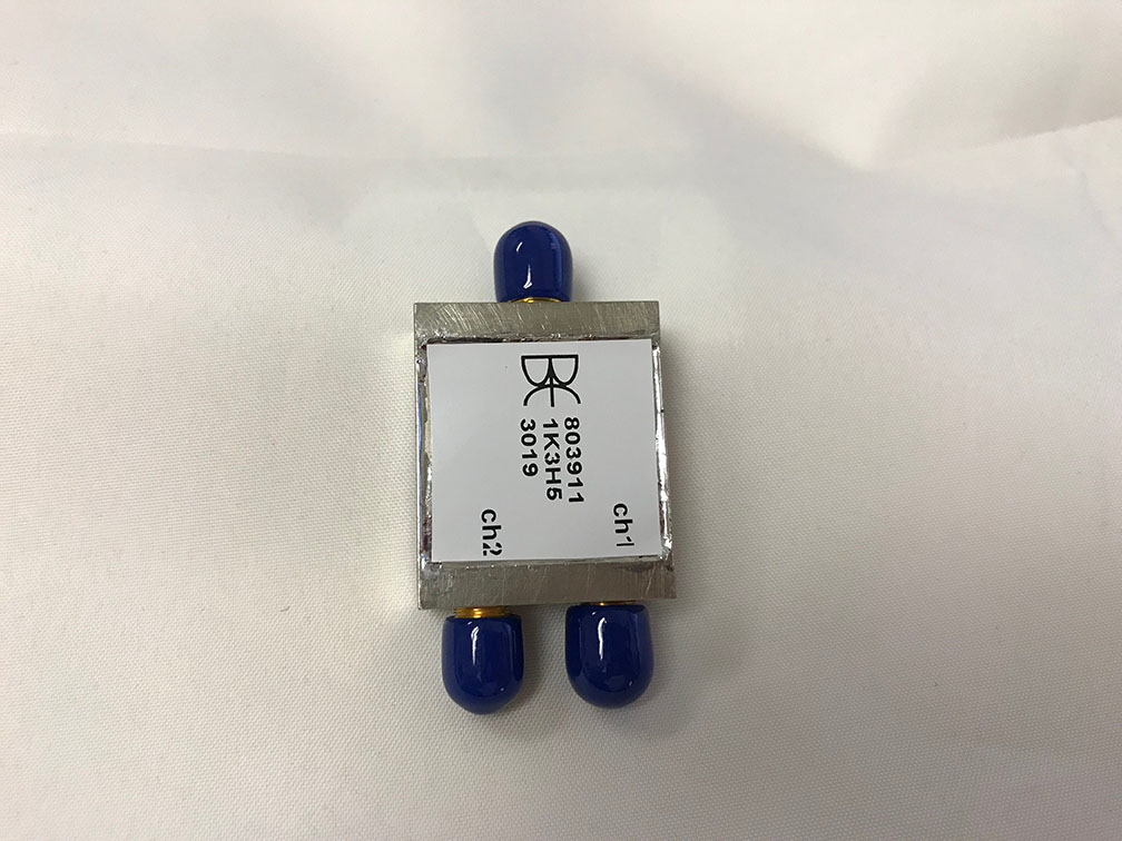
 Multiplexer – Diplexer
This multiplexed diplexer splits the signal between ports 1 and 2. Each channel performs differently and for this particular device we were able to adjust the channel specifications to meet good insertion loss and return loss. This particular device maintains consistent rejection and close to the passband cutoff points.
This diplexer is unique in its extended rejection. As part of the filter specifications, we were asked to carry out the filter performance past 20 GHz and we were able to push it out to 25.5 GHz. The passbands for both channel 1 and channel 2 do a great job at maintaining a consistent Insertion loss and return loss throughout. The typical specifications are met and exceeded on channel 1 holding a greater than 17 dB return loss and less than 1 dB of insertion loss from 1000 to 5000 MHz. Channel 2 has some break points due to the extended passband, but the performance of the diplexer is still upheld per the specifications. From 6500 to 15500 MHz the insertion loss is less than 1.7 dB and from 15500 to 25500 the insertion loss is less than 2.5 dB. The return loss on the equivalent passbands is also maintained to be greater than 14 and 12 dB respectively.
As with all of our Filters here at Bree Engineering the design is custom and tailored to the specifications of our clients. We are always striving to do our best to design, build and tune filters of any type.
Please see the attached Filter Test Data for the performance of the filter.
Package Size: 1.20 x 1.00 x 0.40 Inches
Configuration: SMA-F Connectors
Insertion Loss:
Channel 1: <1.0 dBa 1000 MHz – 5000 MHz
Channel 2: <1.7 dBa 6500 MHz – 15500 MHz
Channel 2: <2.5 dBa 15500 MHz – 25500 MHz
Return Loss:
Channel 1: >17 dB 1000 MHz – 5000 MHz
Channel 2: <14 dBa 6500 MHz – 15500 MHz
Channel 2: <12 dBa 15500 MHz – 25500 MHz
Rejection:
Channel 1: >50 dBc 6500 MHz – 15500 MHz
Channel 1: >40 dBc 15500 MHz – 25500 MHz
Channel 2: >50 dBc 1000 MHz – 5000 MHz
